Stadium LED Display Infrastructure: An Engineering Guide for Venue Systems
Most stadium LED failures aren’t LED failures. They’re power distribution, grounding, and data transmission failures that happen to manifest on the screen. This guide breaks down the stadium LED display infrastructure decisions that determine whether a stadium LED display system runs for 10 years or 3.
When a stadium LED display fails during a live match, the LED modules usually aren’t the culprit. Our field data from over 60 stadium deployments shows that roughly 70% of on-screen defects trace back to stadium LED display infrastructure — specifically power distribution, grounding, and data transmission — not the LED panels themselves. The screen is simply where the failure becomes visible.
This is the blind spot in most stadium LED display system procurement decisions. Buyers focus on pixel pitch, brightness, and refresh rate — all correct concerns — but treat the underlying stadium LED display infrastructure as an afterthought. The result is a display that performs beautifully in the factory demo and develops intermittent faults in month eight.
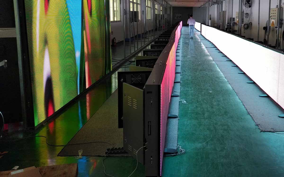
This guide breaks down the four layers of stadium LED display infrastructure that determine the long-term reliability of any installation, from a 60-meter perimeter ring to a 200-square-meter center-hung scoreboard.
Why Infrastructure Matters More Than the LED Panel
An LED panel is a passive component. It draws current from a power supply, receives data from a sending card, and outputs light. When the panel fails, the question is never “why did the panel fail” — it’s “what upstream condition within the stadium LED display infrastructure caused the panel to fail.”
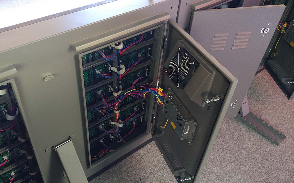
Four infrastructure layers sit between your venue’s main power feed and the LED pixels themselves. Each one has its own failure modes and its own engineering discipline:
Main Power Distribution & Surge Protection
Every stadium LED display power distribution system should be fed from a dedicated distribution board with its own circuit breakers and Type 2 surge protection devices (SPDs). A shared board exposes the display to transients from HVAC, floodlights, and scoreboard motors. For outdoor perimeter systems, add Type 1 SPD at the main incoming feed to handle direct lightning-induced surges.
AC Power Quality & Load Balancing
LED power supplies are switch-mode devices with non-linear load characteristics. They inject harmonics back into the AC line, which can destabilize other equipment and reduce the lifespan of the PSUs themselves. For installations above 50kW total load, install a harmonic filter or active power factor correction. Balance three-phase loads across cabinets to prevent neutral overload — a common cause of intermittent cabinet blackouts.
Data Transmission Architecture
Stadium LED data transmission architecture reaches each cabinet via a chain of sending cards, receiving cards, and Ethernet or fiber links. Long runs of copper Ethernet between distant cabinets are vulnerable to ground potential differences — the silent killer that causes intermittent data dropouts during humid weather. For runs exceeding 80 meters, use fiber optic backbones with media converters at each distribution point. Never share a data backbone with broadcast or scoreboard control systems.
Grounding & Lightning Protection
A single, low-impedance, unified stadium LED grounding system is the foundation of reliability. Multiple ground points with different potentials create circulating currents through the data lines. This is the #1 cause of “random section flicker” complaints. Bond every cabinet frame, every PSU enclosure, and every mounting bracket to the same earth bus. Verify ground resistance annually — a target of <1Ω at each cabinet is achievable and non-negotiable.
The Four-Layer Infrastructure Model
Think of a stadium LED display as an industrial electrical system that happens to emit light. Each layer of stadium LED display infrastructure has a defined specification that should appear in your procurement contract:
| Layer | Specification | Typical Failure Mode |
|---|---|---|
| Main Power Feed | Dedicated DB + Type 1/2 SPD | Surge damage to PSUs after lightning |
| AC Distribution | 3-phase balanced, <3% voltage imbalance | Cabinet flicker, PSU overheating |
| Data Backbone | Fiber >80m, isolated from broadcast network | Intermittent data dropout in high humidity |
| Grounding System | <1Ω unified earth bus | Circulating current flicker, ground loop noise |
Five Common Infrastructure Mistakes in Stadium LED Projects
- Sharing the main distribution board with floodlights. When the floodlights switch on, voltage sags propagate to the display. Install a separate DB with its own breaker and SPD.
- Skipping fiber in favor of long copper runs. Copper looks cheaper on the BOM. It becomes expensive when ground potential differences cause intermittent data dropouts during your first televised match.
- Ignoring harmonic distortion. Switch-mode PSUs generate 3rd and 5th harmonics that overload neutral conductors on shared feeders. Add harmonic filtering above 50kW total LED load.
- Grounding to the building steel instead of a dedicated earth bus. Building steel carries currents from unrelated systems. Always run a dedicated earth conductor to the display’s unified ground bar.
- No fiber-to-copper transition documentation. Every transition point is a potential failure site. Document each one, label it, and include it in your maintenance checklist.
The Infrastructure Procurement Checklist
Use this checklist when evaluating any stadium LED display supplier. If a supplier can’t answer these questions, you’re not buying a system — you’re buying panels with a warranty attached.
Is the main feed dedicated or shared?
Require a dedicated distribution board. Shared feeds create voltage sag and transient coupling.
What SPD type is included at the incoming feed?
Type 1 for outdoor perimeter systems (lightning), Type 2 for indoor installations (switching transients).
Where does the system transition from fiber to copper?
Every transition point should be documented, labeled, and included in the maintenance schedule.
What is the specified ground resistance target?
Target <1Ω at each cabinet, verified during commissioning and annually thereafter.
Is the data backbone isolated from broadcast systems?
Broadcast networks introduce transients that can corrupt LED data. Always run a dedicated backbone.
For a deeper dive into the maintenance side of this infrastructure, see our Stadium Perimeter LED Display Maintenance Guide — the 12-point checklist that keeps this infrastructure running across an 8–10 year service life.
Real Venue Outcome: The Infrastructure Difference
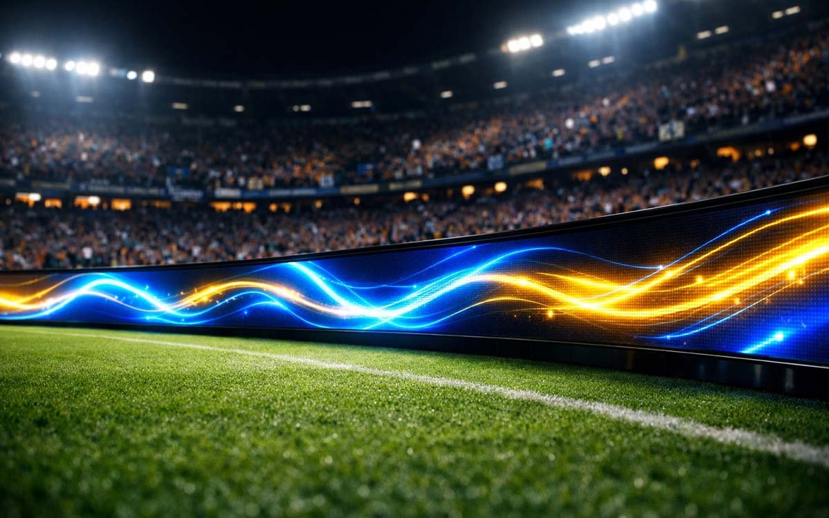
A recent 180-meter P10 perimeter deployment in a Middle Eastern multi-sport venue illustrates the difference. The project team insisted on a dedicated distribution board, fiber backbone above 60 meters, Type 1 SPD at the main feed, and a unified ground bus across all 180 cabinets.
Three seasons later, field data shows:
- Zero unplanned data dropouts during televised matches
- PSU failure rate: 0.2% per year — compared to the 1.8% industry average for shared-feed installations
- No ground-loop flicker events reported across three full seasons
- Electrical commissioning time: 4 days — most of which was spent verifying, not troubleshooting
The stadium LED display infrastructure premium on the BOM was approximately 6% of total project cost. The avoided field-service interventions over three years exceeded that premium by a factor of four.
Key Takeaways for Venue Systems Engineers
- The LED panel is not the weak point. Stadium LED display infrastructure — power, data, and grounding — determines long-term reliability.
- Demand a dedicated distribution board with proper SPD type for your installation environment.
- Use fiber backbones above 80 meters to eliminate ground potential difference failures.
- Specify a unified ground bus with <1Ω resistance at every cabinet — verify annually.
- Include a full stadium LED display electrical specification in your procurement contract. Panel specs alone are not enough.
Related Reading
For deeper context on the systems and standards behind this guide:
- Stadium Perimeter LED Display Maintenance Guide: A 12-Point Annual Checklist — the field-level counterpart to this infrastructure guide.
- How to Choose the Right Pixel Pitch for Your Stadium Display System — P6 vs P8 vs P10 with viewing-distance math.
- Stadium Perimeter LED Boards vs Center-Hung Scoreboards — which surface fits which venue type.
- Why Sub-10ms Sync Matters in Live Sports Displays — the synchronization problem behind multi-screen venues.
External references:
- ICS 31.120 — LED Display Requirements for Sports Venues (China National Standard) — official electrical and data requirements for sports venue displays.
- LED Perimeter Display Maintenance Schedules (LIGHTALL) — industry maintenance planning framework for perimeter systems.
- LED Display Daily Inspection Guide (Sansitech, 2026 World Cup edition) — component-level inspection protocols for high-load events.
Need an Infrastructure Review for Your Next Stadium LED Project?
Send us your venue type, screen dimensions, and total power budget. We’ll come back with a stadium LED display infrastructure gap analysis and a recommended specification package.
Request an Infrastructure Review